

Push Button
IP67-rated tactile push button for the PomeLabs Core Kit.
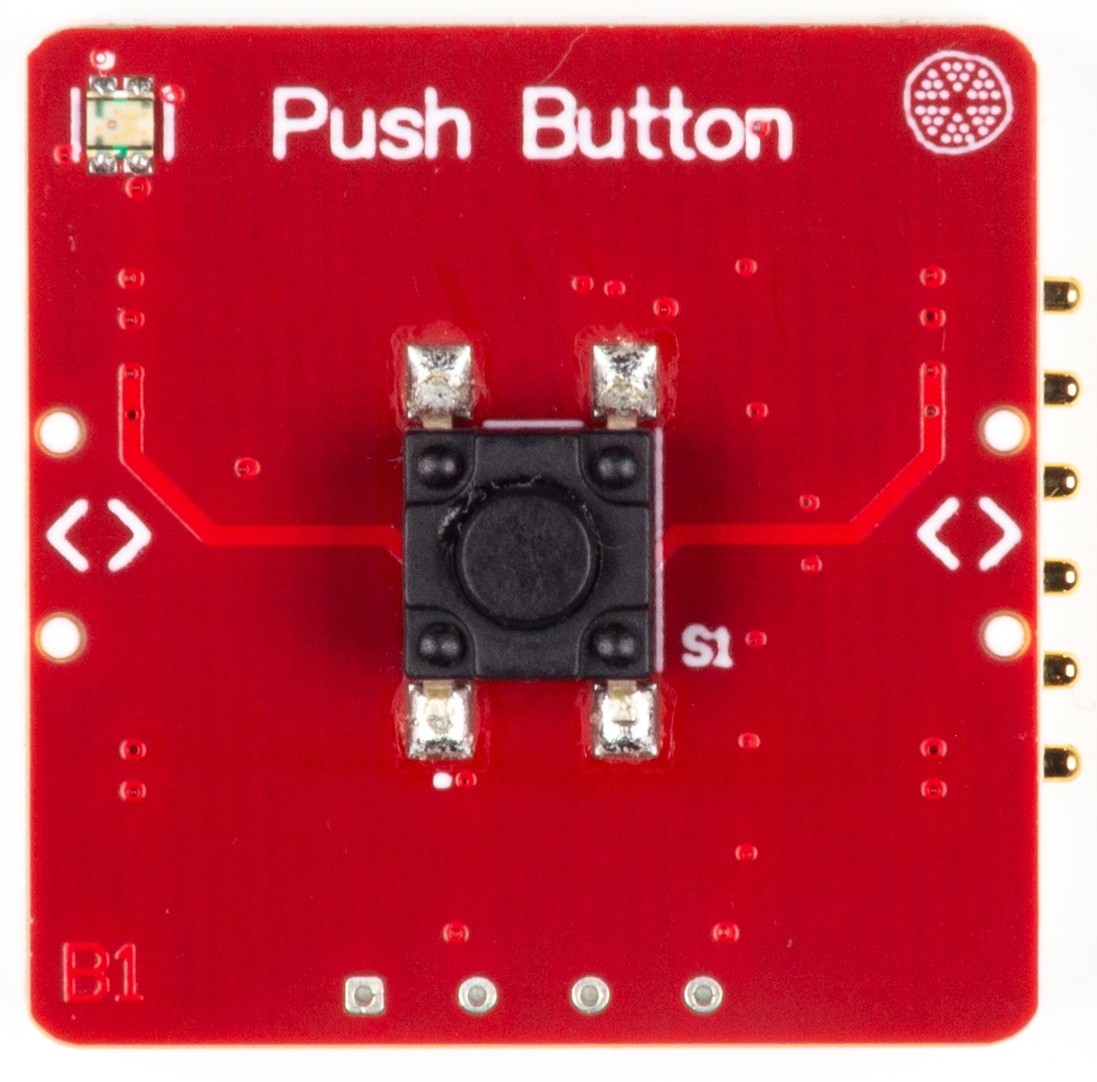
The PomeLabs Push Button Module (PML-PB-01) puts a single, deliberate, physical action at the center of your circuit. Press it and a clean momentary signal appears — IP67-sealed against dust and water, rated for cycles, with two UART ports so the rest of your kit stays connected while you interact.
Revision: v1.0 | Part Number: PML-PB-01 | Series: PomeLabs Core Kit
Schematic

Digital Twin
In the PomeLabs App, the PML-PB-01 is mirrored as a digital twin in both the Playground and inside any Connect Activity. On connection the module reports its unique ID, firmware version, and type, and the App places it in your circuit by reading the live netlist — so you always see which module it is and how it is wired. The button is a passive momentary contact: the App knows the module is present and where it sits, but the current release neither simulates a press nor streams the live contact state.
Datasheet
1. Overview
The PML-PB-01 centers on the TS05-66-50-BK-260-SMT-67 (Same Sky / CUI Devices) — a surface-mount tactile switch rated for mechanical cycles. It is SPST normally-open (NO) and momentary: terminals S1_A and S1_B are electrically open at rest and make contact only while the button is held down, returning to open on release.
The IP67 rating distinguishes this switch from standard tactile components — it is dust-tight and protected against temporary immersion, making it suitable for lab environments where liquid spills or particulate contamination are a real risk. The () operating force provides firm, unambiguous tactile feedback that eliminates accidental actuation during circuit handling.
2. BOM Components
| Ref. | Type | Value / Part | Role on this module |
|---|---|---|---|
| S1 | Tactile switch | TS05-66-50-BK-260-SMT-67 (Same Sky) | SPST normally-open momentary push button. IP67 rated. Black actuator, height, () operating force, SMT body. S1_A and S1_B open at rest; contact made only while button is held. cycle mechanical life. Brass terminals (silver-plated); SUS contacts (silver-plated). |
| R1, R2 | Resistor | Pull-up resistors on UART TX/RX lines to . | |
| p1, p2 | Connector | Node headers | Left and Right node connectors exposing , GND, S+, S−, RX/TX, TX/RX to downstream modules. |
3. Electrical Specifications
Switch specifications from Same Sky TS05 series datasheet.
3.1 TS05-66-50-BK-260-SMT-67
The TS05-66-50-BK-260-SMT-67 is a surface-mount tactile switch with a actuator height. The following specifications are derived from manufacturer datasheets and distributor technical data.
3.1.1 Absolute Maximum Ratings
Exceeding these ratings may cause permanent damage to the device.
| Parameter | Symbol | Value | Unit |
|---|---|---|---|
| Voltage Rating (across open contacts) | VDC | ||
| Current Rating (through closed contacts) | mA | ||
| Operating Temperature | to | °C | |
| Storage Temperature | to | °C | |
| Mechanical Life (cycles) | — | ||
| Electrical Life (cycles) | — |
3.1.2 Recommended Operating Conditions
Recommended conditions for reliable operation.
| Parameter | Symbol | Min | Typ | Max | Unit |
|---|---|---|---|---|---|
| Supply Voltage | — | VDC | |||
| Operating Current | — | mA | |||
| Operating Force | — | () | — | gf | |
| Switch Travel (Actuator stroke) | — | — | mm | ||
| Contact Resistance | — | — | m | ||
| Insulation Resistance () | — | — | M | ||
| Dielectric Strength ( minute) | — | — | VAC | ||
| Bounce Time (typical) | — | — | ms |
4. Pin Descriptions
All signal pins are referenced to GND.
| Pin / Net Name | Direction | Description |
|---|---|---|
| S1_A | Passive | Terminal A of switch S1. One side of the SPST momentary contact. Connect to signal source or pull-up/pull-down circuit. |
| S1_B | Passive | Terminal B of switch S1. Connected to the opposing rail (GND or signal destination). Electrically connected to S1_A only when button is pressed. |
| TX_L-1 / TX_L-2 | Input | UART transmit from Backend MCU (USART1/USART3) to Left and Right node connectors. |
| RX_L-1 / RX_L-2 | Output | UART receive from Left and Right node connectors back to Backend MCU. |
| TX_P-1 / TX_P-2 | Output | Transmit lines to node-side connectors. |
| RX_P-1 / RX_P-2 | Input | Receive lines from node connectors. |
| 5VBus | Power In | supply rail. |
| 3V3 | Power In | logic rail for pull-up resistors R1–R2 (). |
| GND | Ground | Common ground reference for all components and connectors. |
5. Connection Guide & Common Errors
Correct wiring and power-up sequence:
- Connect GND first, shared across all modules on the common bus.
- Connect 5VBus to a regulated source.
- Connect 3V3 for UART pull-up resistors R1 and R2.
- Connect S1_A to signal source (e.g. via pull-up to VCC). Connect S1_B to GND for active-low configuration.
- Configure Backend MCU GPIO as input with pull-up/pull-down to avoid floating input.
- Do not exceed or through the switch contacts.
Common wiring errors and consequences:
| Mistake | Symptom | Correction |
|---|---|---|
| Voltage on S1 terminals exceeds | Contact degradation or arcing; switch permanently damaged | Keep switched voltage . |
| Current through S1 exceeds | Contact welding or burning; switch fails open or stuck closed | Keep switched current . Add series resistor if load current may exceed this. |
| Switch input node left floating (no pull-up or pull-down) | Floating CMOS input on Backend MCU — undefined logic level | Always connect a pull-up or pull-down resistor on the GPIO reading S1. Typical . |
| More than reflow cycles applied to S1 | Switch housing or waterproof seal may be damaged; IP67 rating voided | Limit reflow soldering to a maximum of cycles per TS05 assembly specification. |
How is this guide?