

Node Multiplier
4-port UART node expander for the PomeLabs Core Kit.
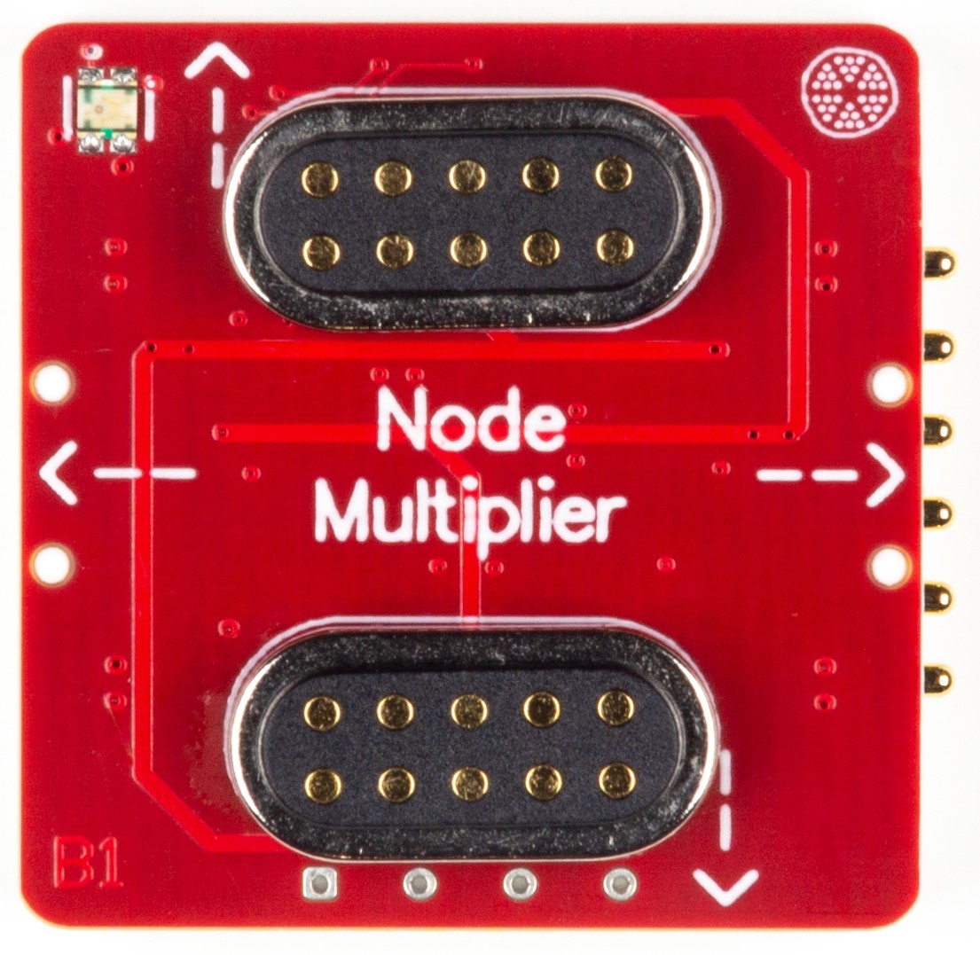
The PomeLabs Node Multiplier Module (PML-NM-01) turns one Backend MCU into a four-node communication hub. Each port gets its own independent UART channel — so you can run four simultaneous serial conversations without any shared risk, any external components, or any compromise on signal integrity.
Revision: v1.0 | Part Number: PML-NM-01 | Series: PomeLabs Core Kit
Schematic

Digital Twin
In the PomeLabs App, the PML-NM-01 is mirrored as a digital twin in both the Playground and inside any Connect Activity. On connection the module reports its unique ID, firmware version, and type, and the App places it in your circuit by reading the live netlist — so you always see which module it is and how it is wired. The module's four-way UART fan-out to downstream nodes is pure connectivity; it carries no digital I/O of its own beyond identity, so the current release exposes no app-side controls or streamed values for this module.
Datasheet
1. Overview
The PML-NM-01 enables a single Backend MCU to communicate with up to four independent downstream nodes simultaneously using four independent USART channels (USART1–USART4).
Ports 3 and 4 connect to field-side expansion nodes via 10-pin Magnetic Female Pogo connectors (J1NM, J2NM) inside a dedicated FE Function sub-block. Ports 1 and 2 connect to the upper pin-header connectors (P1, P2) on the module edge.
The architecture is deliberately symmetric — every port is treated identically in terms of pull-up biasing, so any port can be assigned to any node without electrical asymmetry.
2. BOM Components
| Ref. | Type | Value / Part | Role on this module |
|---|---|---|---|
| J1NM, J2NM | Connector | 10-Pin Magnetic Female Pogo | Node-side interface connectors for Ports 3 and 4 (FE Function block). Carry +5V, GND, S+/S−, and TX/RX signals between modules with self-aligning magnetic mating. |
| P1, P2 | Connector | Pin headers | Edge-side interface connectors for Ports 1 and 2. Expose +5V, GND, S+/S−, RX/TX, TX/RX. |
| R1–R4 | Resistor | Pull-up resistors on the node-side TX/RX lines, biased to 3V3. Hold the lines in a defined HIGH state when no node is connected. |
3. Electrical Specifications
All values at = unless otherwise noted. Pogo connector specifications are typical for industry-standard 10-pin magnetic spring-loaded connectors; consult the connector manufacturer's datasheet for the exact values used in production.
3.1 J1NM, J2NM — 10-Pin Magnetic Female Pogo Connector
Industry-typical specifications for 10-pin magnetic pogo connectors. Confirm against the connector vendor's datasheet for the production part.
| Parameter | Typical Value | Notes |
|---|---|---|
| Number of contacts | Female receptacle, spring-pin mating | |
| Contact resistance | Per pin, after mating cycles | |
| Rated current per pin | – | Depends on pin construction; verify against vendor datasheet |
| Insulation resistance | At DC | |
| Mating cycles | Typical durability rating | |
| Operating temperature | to | Industry-standard range |
| Spring force (per pin) | – | Typical range at working stroke |
| Mating alignment | Magnetic, self-aligning | Reverses orientation safely (verify magnet polarity) |
4. Pin Descriptions
All signal pins are referenced to GND.
| Pin / Net Name | Direction | Description |
|---|---|---|
| TX_1-L … TX_4-L | Input | UART transmit inputs from Backend MCU (USART1–USART4 TX). Each line carries outbound serial data for the corresponding node port. |
| RX_1-L … RX_4-L | Output | UART receive outputs back to Backend MCU (USART1–USART4 RX). Each line carries inbound serial data from the corresponding node port. |
| TX_*-P | Output | Transmit lines to node-side connectors. For Ports 1–2 these go to P1/P2; for Ports 3–4 they go to J1NM/J2NM. |
| RX_*-P | Input | Receive lines from node-side connectors. For Ports 1–2 these come from P1/P2; for Ports 3–4 from J1NM/J2NM. |
| 5V-Bus | Power In | supply rail. Powers the +5V pin of all four port connectors. |
| 3V3 | Power In | logic rail used by the pull-up resistors R1–R4 () on the node-side TX/RX lines. |
| GND | Ground | Common ground. Shared across the Backend MCU and all connectors. |
| R1–R4 () | Passive | Pull-up resistors on the node-side TX/RX lines to 3V3. Keep the lines at a defined HIGH idle state when no node is connected; also help suppress mid-rail noise. |
5. Connection Guide & Common Errors
Correct power-up sequence:
- Connect GND first, ensuring it is shared across the Backend MCU, the Node Multiplier, and any downstream node modules on the common bus.
- Connect 5V-Bus to a regulated source. This rail supplies the +5V pin of all four port connectors.
- Connect the 3V3 rail. The pull-up resistors R1–R4 use this rail to hold the idle UART lines HIGH.
- Connect downstream nodes only after the supply rails are stable. Magnetic Pogo connectors (J1NM, J2NM) self-align — verify the magnet polarity is correct before forcing a mate.
- Verify TX from the Backend MCU connects to RX on the downstream node and vice-versa (cross-wired UART). The labelling on the P1/P2 headers and Pogo pinouts assumes this convention.
Common wiring errors and consequences:
| Mistake | Symptom | Correction |
|---|---|---|
| GND not shared across MCU, Node Multiplier, and downstream nodes | Ground offset corrupts UART signal levels (framing errors, wrong logic levels) | Ensure a single common GND bus shared between the Backend MCU and every connected node module. Avoid star-ground topologies with thin return traces. |
| TX and RX swapped at a connector | No communication; UART framing errors or silence | Verify TX from the MCU side maps to RX of the downstream node (and vice-versa) at each connector. Pogo connectors are not symmetrical despite the magnetic mating — confirm pinout. |
| Pull-ups R1–R4 not biased to 3V3 (rail unconnected) | Idle UART lines float; spurious break or framing detection on disconnected ports | Connect the 3V3 rail. The pull-ups hold the lines at a clean HIGH between transmissions and when a port has no node attached. |
| Pogo connector mated dirty / dusty | Increased contact resistance — UART signal degradation, intermittent comms | Wipe the female receptacle and the mating pads periodically with isopropyl alcohol. Magnetic pogo connectors are typically rated for mating cycles when kept clean. |
How is this guide?