

NOT Gate
3-state logic inverter with Schmitt-trigger input for the PomeLabs Core Kit.
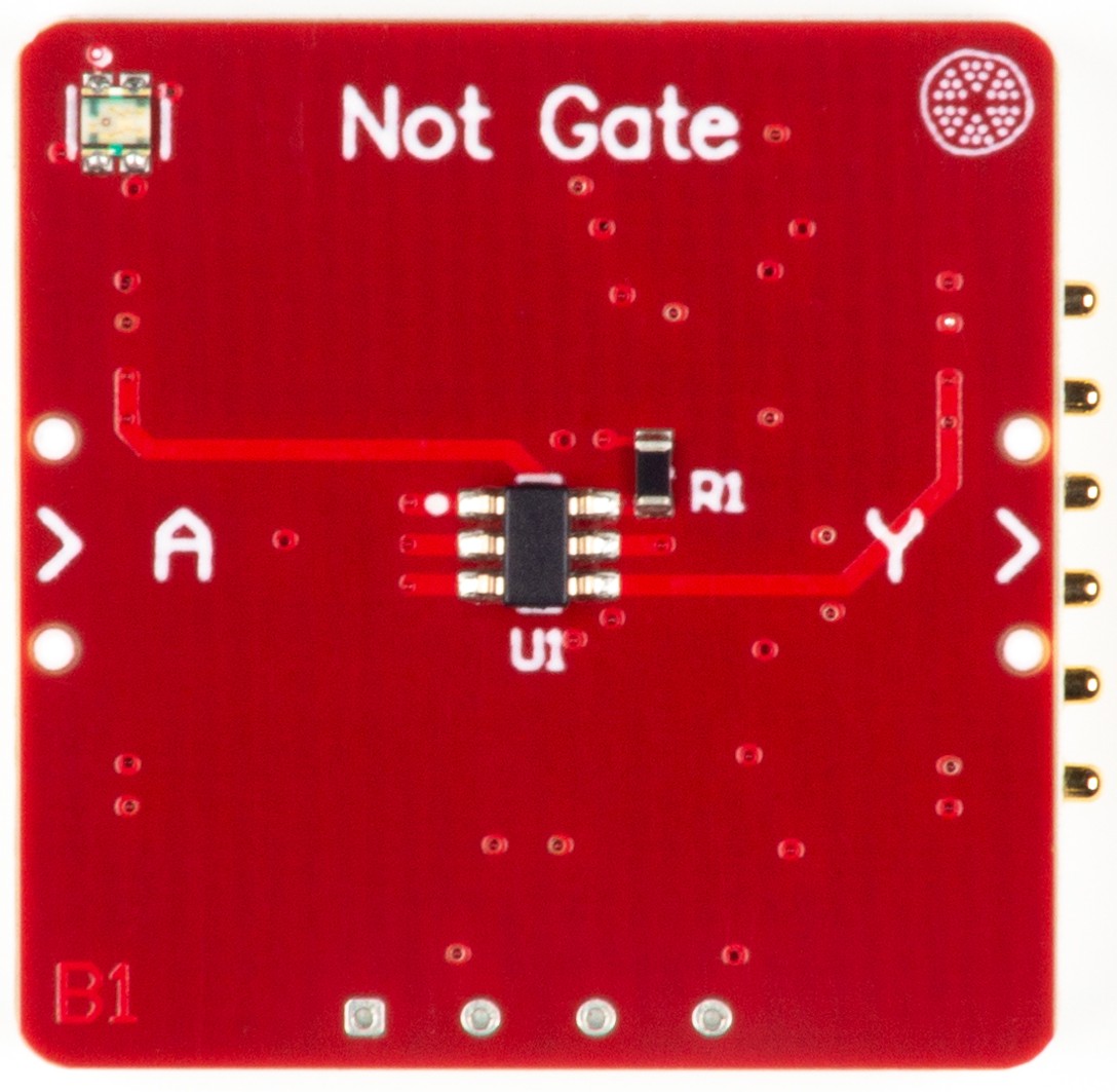
The PomeLabs NOT Gate Module (PML-NG-01) is the simplest possible logic operation made into a standalone educational building block. One input in, its complement out — every time, unconditionally. The same configurable IC powers the AND and XOR Gate Modules in this kit; here it is wired as a precision Schmitt-trigger inverter with output drive.
Revision: v1.0 | Part Number: PML-NG-01 | Series: PomeLabs Core Kit
Schematic

Digital Twin
In the PomeLabs App, the PML-NG-01 is mirrored as a digital twin in both the Playground and inside any Connect Activity. On connection the module reports its unique ID, firmware version, and type, and the App places it in your circuit by reading the live netlist — so you always see which module it is and how it is wired. Its combinational logic runs entirely on the physical gate IC; the current release exposes no app-side controls or streamed values for this module.
Datasheet
1. Overview
The PML-NG-01 implements a logic inverter using the SN74LVC1G99DCUR (U1) — the same ultra-configurable single-gate device used in the AND Gate Module, here configured as a 3-state inverter (NOT gate). On this module, configuration pin D is hard-tied HIGH and pin C is hard-tied LOW on the PCB; OE is hard-tied LOW. Input pin A receives the user signal, and pin B is a "don't-care" per the TI Function Selection Table (the inverter row accepts B = H or L when this configuration is chosen).
When input A (S+_L) is HIGH, output Y (S+_R) is LOW. When A is LOW, Y is HIGH — the output is always the logical complement of the input. The Schmitt-trigger input stage ( hysteresis typ at = ) cleanly handles slow or noisy signals without spurious output transitions.
Comparing the configuration of this module with the AND Gate Module reveals how a single IC delivers fundamentally different logic functions by changing only two pin tie-offs — a practical demonstration of programmable logic principles.
2. BOM Components
| Ref. | Type | Value / Part | Role on this module |
|---|---|---|---|
| U1 | Configurable logic gate | SN74LVC1G99DCUR (TI) | Configured as 3-state inverter: OE = GND, A = Input, B = don't care, C = GND, D = . Schmitt-trigger input ( hysteresis typ at = ). VSSOP-8 (DCU) package, . |
| R1 | Resistor | Pull-up resistor on Left-port UART line to 3V3. Holds the line at a defined HIGH idle state when no node is connected. | |
| R2 | Resistor | Pull-up resistor on Right-port UART line to 3V3. Identical role to R1. | |
| p1, p2 | Connector | Node headers | Left and Right node connectors exposing +5V, GND, S+, S−, RX/TX, TX/RX. |
3. Electrical Specifications
All values at unless otherwise noted. Gate specifications from TI SCES609G (SN74LVC1G99, Rev. G, Nov 2013).
3.1 U1 — SN74LVC1G99DCUR
The SN74LVC1G99 features configurable multiple functions with a 3-state output. The output is disabled when the output-enable (OE) input is HIGH. When OE is LOW, the output state is determined by 16 patterns of the 4-bit input (A, B, C, D). Selectable functions include MUX, AND, OR, NAND, NOR, XOR, XNOR, inverter, and buffer. All inputs can be connected to or GND.
3.1.1 Absolute Maximum Ratings
Exceeding these values may permanently damage the device. Stress ratings only.
| Parameter | Max Value | Unit |
|---|---|---|
| Supply voltage () | to | V |
| Input voltage () | to | V |
| Output voltage — high-Z or power-off state () | to | V |
| Output voltage — high or low state () | to | V |
| Input clamp current (), | mA | |
| Output clamp current (), | mA | |
| Continuous output current () | mA | |
| Continuous current through or GND | mA | |
| Package thermal impedance () — DCU package | °C/W | |
| Storage temperature () | to | °C |
3.1.2 Recommended Operating Conditions
| Parameter | Min | Max | Unit / Notes |
|---|---|---|---|
| Supply voltage () — operating | V | ||
| Supply voltage () — data retention only | — | V | |
| Input voltage () | V — input accepts up to regardless of | ||
| Output voltage () | V | ||
| High-level output current () @ = | — | mA — sourcing | |
| Low-level output current () @ = | — | mA — sinking | |
| High-level output current () @ = | — | mA — sourcing | |
| Low-level output current () @ = | — | mA — sinking | |
| Input transition rise/fall rate () @ = | — | ns/V | |
| Operating temperature () | °C |
3.1.3 Electrical Characteristics
| Parameter | Typical | Max | Condition |
|---|---|---|---|
| Positive-going input threshold () | — | = — Schmitt trigger | |
| Negative-going input threshold () | — | = | |
| Input hysteresis () | = | ||
| Propagation delay () A → Y | — | = , = | |
| Propagation delay () D → Y | — | = , = | |
| Propagation delay () A → Y | — | = , = | |
| Output enable time () | — | = , = | |
| Output disable time () | — | = , = | |
| Quiescent supply current () | — | = or GND, = | |
| Input capacitance () | — | = | |
| Output capacitance () | — | = | |
| Power dissipation capacitance () | — | = , = |
4. Truth Table
On this module, OE = L, C = L, and D = H are hard-tied on the PCB — selecting the 3-state inverter function. Pin B is a don't-care for this configuration. The output is therefore the logical complement of input A:
| OE | A (S+_L) | B | C | D | Y Output (S+_R) |
|---|---|---|---|---|---|
| L | L | X | L | H | H — input LOW → output HIGH (inverted) |
| L | H | X | L | H | L — input HIGH → output LOW (inverted) |
The high-impedance state (Y = Z) is not reachable on this module because OE is hardwired LOW.
5. Logic Function Configuration Reference
The SN74LVC1G99 supports nine distinct logic functions selected by the static levels on A, B, C, D, and OE. The table below shows common configurations for reference — only the inverter configuration is wired on this PCB.
| Function | OE | A | B | C | D |
|---|---|---|---|---|---|
| 3-state inverter / NOT (this module) | L | Input | H or L | L | H |
| 3-state buffer | L | Input | H or L | L | L |
| 3-state 2-input AND | L | Input 1 | Input 2 | L | L |
| 3-state 2-input NAND | L | Input 1 | Input 2 | H | L |
| 3-state 2-input OR | L | Input 1 | H | Input 2 | L |
| 3-state 2-input NOR | L | Input 1 | H | Input 2 | H |
| 3-state 2-input XOR | L | Input 1 | L | Input 2 | H |
| 3-state 2-input XNOR | L | H | L | Input 1 | Input 2 |
| Output disabled (high-Z) | H | X | X | X | X |
6. Pin Descriptions
All signal pins are referenced to GND.
| Pin / Net Name | Direction | Description |
|---|---|---|
| S+_L | Input | Logic input A to U1. Left channel — the single input to the inverter. When HIGH, Y goes LOW; when LOW, Y goes HIGH. |
| S+_R | Output | Inverter output Y. Logic complement of S+_L (OE is hardwired LOW). |
| TX_L/1 | Input | UART transmit from Backend MCU to Left port. |
| RX_L/1 | Output | UART receive from Left connector back to Backend MCU. |
| TX_R/2 | Input | UART transmit from Backend MCU to Right port. |
| RX_R/2 | Output | UART receive from Right connector back to Backend MCU. |
| 5V-Module | Power In | supply. Powers of U1. |
| 3V3 | Power In | logic rail for pull-up resistors R1 and R2 ( each). |
| GND | Ground | Common ground for all ICs and connectors. |
7. Connection Guide & Common Errors
Correct power-up sequence:
- Connect GND first, shared across all modules on the common bus.
- Connect 5V-Module to a regulated source. This powers of U1.
- Connect the 3V3 rail for the UART pull-up resistors R1 and R2.
- Apply a logic signal to S+_L (input A). The inverted output appears immediately on S+_R — there is no enable step because OE is hardwired LOW on the PCB.
Logic-level reference (Schmitt-trigger input): at = , the input must rise above to register as HIGH (driving Y LOW) and fall below to register as LOW (driving Y HIGH). Signals stuck inside the hysteresis band (–) hold the previous logic state — useful for noise immunity, especially relevant when chaining multiple NOT gates into a ring oscillator where sub-threshold noise could otherwise propagate as glitches.
Common wiring errors and consequences:
| Mistake | Symptom | Correction |
|---|---|---|
| Input S+_L left floating | Floating CMOS input drifts within the hysteresis band; output may oscillate randomly or hold an indeterminate state | Always drive S+_L from a defined logic source. Add a pull-down or pull-up resistor if the upstream signal source can disconnect. |
| to U1 exceeds | U1 permanently damaged (absolute max ) | Keep 5V-Module rail . |
| Input signal on S+_L exceeds | Input clamp current flows; permanent damage if exceeds | Input is tolerant — never exceed it. Add a series resistor if your source can swing higher than . |
| Output Y driving load | Continuous output current absolute max exceeded — U1 may overheat or fail | Keep on S+_R within absolute max. For sustained operation, design for at or at . Ring oscillator chains lightly load each stage and stay well within spec. |
| Very slow input edges (slower than at ) | Operation outside the guaranteed input transition rate; the Schmitt-trigger hysteresis improves robustness but TI does not specify behavior beyond this rate | Buffer slow analog-like signals with another logic stage if reliability is critical. The Schmitt input handles edges much slower than a plain CMOS input would, but is not unlimited. |
| Powering input S+_L while 5V-Module is OFF | circuitry isolates U1 and prevents back-drive damage — designed-in safe condition, not a fault | No action needed; partial-power-down via is supported by the device. |
Note: OE, C, and D are hard-tied to GND/ on the PCB and are not user-accessible. The common floating-input mistakes that apply to bare SN74LVC1G99 designs (floating OE → high-Z output; floating C/D → undefined function) do not apply to this assembled module. Pin B is a don't-care for the inverter configuration and is also tied off on the PCB.
How is this guide?